概要
今回は”BMP”、"JPEG"、"PNG" フォーマットの画像をLCDに表示します。
BITMAP関係
drawXBitmap.ino
IDE でファイルー>スケッチ例ー>TFT_eSPIー>Genericー>drawXBitmap にデモプログラムが有ります。
// Example sketch to demonstrate the drawing of X BitMap (XBM)
// format image onto the display.

// Information on the X BitMap (XBM) format can be found here:
// https://en.wikipedia.org/wiki/X_BitMap

// This example is part of the TFT_eSPI library:
// https://github.com/Bodmer/TFT_eSPI

// Created by Bodmer 23/04/18

#include "xbm.h"             // Sketch tab header for xbm images

#include <TFT_eSPI.h>        // Hardware-specific library

TFT_eSPI tft = TFT_eSPI();   // Invoke library


void setup()
{
  tft.begin();               // Initialise the display
  tft.fillScreen(TFT_BLACK); // Black screen fill
}

void loop()
{

  // Example 1
  // =========
  // Random x and y coordinates
  int x = random(tft.width()  - logoWidth);
  int y = random(tft.height() - logoHeight);

  // Draw bitmap with top left corner at x,y with foreground only color
  // Bits set to 1 plot as the defined color, bits set to 0 are not plotted
  //              x  y  xbm   xbm width  xbm height  color
  tft.drawXBitmap(x, y, logo, logoWidth, logoHeight, TFT_WHITE);

  delay(500);

  // Erase old one by drawing over with background colour
  tft.drawXBitmap(x, y, logo, logoWidth, logoHeight, TFT_BLACK);


  // Example 2
  // =========
  // New random x and y coordinates
  x = random(tft.width()  - logoWidth);
  y = random(tft.height() - logoHeight);

  // Draw bitmap with top left corner at x,y with foreground and background colors
  // Bits set to 1 plot as the defined fg color, bits set to 0 are plotted as bg color
  //              x  y  xbm   xbm width  xbm height  fg color   bg color
  tft.drawXBitmap(x, y, logo, logoWidth, logoHeight, TFT_WHITE, TFT_RED);

  delay(500);

  // Erase old one by drawing over with background colour
  tft.drawXBitmap(x, y, logo, logoWidth, logoHeight, TFT_BLACK, TFT_BLACK);

}
// Images can be converted to XBM format by using the online converter here:
// https://www.online-utility.org/image/convert/to/XBM

// The output must be pasted in a header file, renamed and adjusted to appear
// as as a const unsigned char array in PROGMEM (FLASH program memory).

// The xbm format adds padding to pixel rows so they are a whole number of bytes
// In this example 50 pixel width means 56 bits = 7 bytes
// the 50 height then means array uses 50 x 7 = 350 bytes of FLASH
// The library ignores the padding bits when drawing the image on the display.

// Example of the correct format is shown below

// Espressif logo 50 x 50 pixel array in XBM format
#define logoWidth  50  // logo width
#define logoHeight 50  // logo height

// Image is stored in this array
PROGMEM const unsigned char logo[] = {
  0x00, 0x00, 0x00, 0x00, 0x00, 0x00, 0x00, 0x00, 0x00, 0x00, 0x00, 0x00,
  0x00, 0x00, 0x00, 0x00, 0x00, 0x00, 0x00, 0x00, 0x00, 0x00, 0x00, 0x00,
  0x00, 0x00, 0x00, 0x00, 0x00, 0x00, 0x00, 0x00, 0x00, 0x00, 0x00, 0x00,
  0x00, 0x00, 0x3F, 0x00, 0x00, 0x00, 0x00, 0x00, 0x00, 0xFF, 0x01, 0x00,
  0x00, 0x00, 0x00, 0x07, 0xFC, 0x07, 0x00, 0x00, 0x00, 0x82, 0x7F, 0xF0,
  0x1F, 0x00, 0x00, 0x00, 0xC6, 0xFF, 0xC3, 0x3F, 0x00, 0x00, 0x00, 0xE7,
  0xFF, 0x8F, 0x7F, 0x00, 0x00, 0x80, 0xE3, 0xFF, 0x1F, 0xFE, 0x00, 0x00,
  0x80, 0xE1, 0xFF, 0x7F, 0xFC, 0x01, 0x00, 0xC0, 0x00, 0xFF, 0xFF, 0xF8,
  0x03, 0x00, 0xE0, 0x00, 0xE0, 0xFF, 0xF1, 0x03, 0x00, 0x60, 0xF0, 0x81,
  0xFF, 0xE3, 0x07, 0x00, 0x60, 0xFC, 0x1F, 0xFE, 0xC7, 0x07, 0x00, 0x30,
  0xFE, 0x7F, 0xF8, 0x8F, 0x0F, 0x00, 0x30, 0xFF, 0xFF, 0xF1, 0x9F, 0x0F,
  0x00, 0xB0, 0xFF, 0xFF, 0xE3, 0x3F, 0x0F, 0x00, 0xB0, 0xFF, 0xFF, 0xC7,
  0x3F, 0x1E, 0x00, 0xB8, 0xFF, 0xFF, 0x8F, 0x7F, 0x1E, 0x00, 0x98, 0x1F,
  0xFC, 0x3F, 0xFF, 0x1C, 0x00, 0xB8, 0x3F, 0xE0, 0x3F, 0xFE, 0x1C, 0x00,
  0x98, 0xFF, 0xC3, 0x7F, 0xFE, 0x19, 0x00, 0x98, 0xFF, 0x0F, 0xFF, 0xFC,
  0x19, 0x00, 0x38, 0xFF, 0x3F, 0xFF, 0xFC, 0x01, 0x00, 0x30, 0xFE, 0x7F,
  0xFE, 0xF9, 0x03, 0x00, 0x30, 0xFC, 0xFF, 0xFC, 0xF9, 0x03, 0x00, 0x30,
  0xF8, 0xFF, 0xF8, 0xF3, 0x03, 0x00, 0x30, 0x00, 0xFF, 0xF9, 0xF3, 0x03,
  0x00, 0x70, 0x00, 0xFC, 0xF9, 0xF3, 0x07, 0x00, 0x60, 0x00, 0xF8, 0xF3,
  0xF3, 0x07, 0x00, 0xE0, 0xF8, 0xF8, 0xF3, 0xF7, 0x03, 0x00, 0xC0, 0xF8,
  0xF1, 0xF3, 0xE3, 0x03, 0x00, 0xC0, 0xFD, 0xF1, 0xF3, 0xF7, 0x01, 0x00,
  0x80, 0xFD, 0xF1, 0xF3, 0xE7, 0x00, 0x00, 0x00, 0xFF, 0xF1, 0xF3, 0x07,
  0x00, 0x00, 0x00, 0xFF, 0xF8, 0xF3, 0x07, 0x00, 0x00, 0x00, 0x7E, 0xF8,
  0xF3, 0x83, 0x03, 0x00, 0x00, 0x3C, 0xF8, 0xF3, 0xC3, 0x01, 0x00, 0x00,
  0x70, 0xF8, 0xF9, 0xE3, 0x00, 0x00, 0x00, 0xE0, 0xE1, 0x41, 0x78, 0x00,
  0x00, 0x00, 0xC0, 0x0F, 0x00, 0x1F, 0x00, 0x00, 0x00, 0x00, 0xFF, 0xFD,
  0x07, 0x00, 0x00, 0x00, 0x00, 0xF8, 0xFF, 0x01, 0x00, 0x00, 0x00, 0x00,
  0x80, 0x16, 0x00, 0x00, 0x00, 0x00, 0x00, 0x00, 0x00, 0x00, 0x00, 0x00,
  0x00, 0x00, 0x00, 0x00, 0x00, 0x00, 0x00, 0x00, 0x00, 0x00, 0x00, 0x00,
  0x00, 0x00, };
このデモを実行するとLCDにLOGOマーク(下記2種類)が任意の位置に表示されます。

この画像は、関数
drawXBitmap(int16_t x, int16_t y, const uint8_t *bitmap, int16_t w, int16_t h, uint16_t color)
によって表示されています。関数の引数は以下の通り。
| 引数 | 説明 |
|---|---|
| int16_t x | 表示位置X座標(画像左上隅基準) |
| int16_t y | 表示位置Y座標(画像左上隅基準) |
| const uint8_t *bitmap | BitMapデータ開始のポインタ |
| int16_t w | 画像の幅 |
| int16_t h | 画像の高さ |
| int16_t color | 色指定 |
BitMapデータは、ファイル "xbm.h" の配列 "logo[]" として定義されています。 このデータを2進数(0,1)で書き直すと以下の様になります。
00000000000000000000000000000000000000000000000000000000
00000000000000000000000000000000000000000000000000000000
00000000000000000000000000000000000000000000000000000000
00000000000000000000000000000000000000000000000000000000
00000000000000000000000000000000000000000000000000000000
00000000000000000000000011111100000000000000000000000000
00000000000000000000000011111111100000000000000000000000
00000000000000001110000000111111111000000000000000000000
00000000010000011111111000001111111110000000000000000000
00000000011000111111111111000011111111000000000000000000
00000000111001111111111111110001111111100000000000000000
00000001110001111111111111111000011111110000000000000000
00000001100001111111111111111110001111111000000000000000
00000011000000001111111111111111000111111100000000000000
00000111000000000000011111111111100011111100000000000000
00000110000011111000000111111111110001111110000000000000
00000110001111111111100001111111111000111110000000000000
00001100011111111111111000011111111100011111000000000000
00001100111111111111111110001111111110011111000000000000
00001101111111111111111111000111111111001111000000000000
00001101111111111111111111100011111111000111100000000000
00011101111111111111111111110001111111100111100000000000
00011001111110000011111111111100111111110011100000000000
00011101111111000000011111111100011111110011100000000000
00011001111111111100001111111110011111111001100000000000
00011001111111111111000011111111001111111001100000000000
00011100111111111111110011111111001111111000000000000000
00001100011111111111111001111111100111111100000000000000
00001100001111111111111100111111100111111100000000000000
00001100000111111111111100011111110011111100000000000000
00001100000000001111111110011111110011111100000000000000
00001110000000000011111110011111110011111110000000000000
00000110000000000001111111001111110011111110000000000000
00000111000111110001111111001111111011111100000000000000
00000011000111111000111111001111110001111100000000000000
00000011101111111000111111001111111011111000000000000000
00000001101111111000111111001111111001110000000000000000
00000000111111111000111111001111111000000000000000000000
00000000111111110001111111001111111000000000000000000000
00000000011111100001111111001111110000011100000000000000
00000000001111000001111111001111110000111000000000000000
00000000000011100001111110011111110001110000000000000000
00000000000001111000011110000010000111100000000000000000
00000000000000111111000000000000111110000000000000000000
00000000000000001111111110111111111000000000000000000000
00000000000000000001111111111111100000000000000000000000
00000000000000000000000101101000000000000000000000000000
00000000000000000000000000000000000000000000000000000000
00000000000000000000000000000000000000000000000000000000
00000000000000000000000000000000000000000000000000000000
スケッチでは "logo[]" の ”1” の部分の色を "uint16_t color" で指定して表示している様です。
デモプログラムは以下の通り。
- 先ず、"tft.drawXBitmap(x, y, logo, logoWidth, logoHeight, TFT_WHITE);" を実行
- データの”1”の部分の色をTFT_WHITEに指定しています。
- バックが黒なので実行結果は上記画像左(黒と白のLOGO)となります。
- 次に時間を置いて "tft.drawXBitmap(x, y, logo, logoWidth, logoHeight, TFT_BLACK);" を実行
- 今度はデータの”1”の部分の色をTFT_BLACK(黒)に指定しています。
- バックと同じ色なので結果としてLOGOが消えます。
- 次に.drawXBitmap(x, y, logo, logoWidth, logoHeight, TFT_RED, TFT_WHITE);が実行
- これは新たに引数、TFT_WHITEが追加された関数で、こちらはデータの”0”の部分の色を指定します。
- これでデータの”1”の部分はTFT_RED。”0”の部分はTFT_WHITEが指定された事になり上記画像右(赤いLOGO)が表示されます。
- 次に.drawXBitmap(x, y, logo, logoWidth, logoHeight, TFT_BLACK, TFT_BLACK); を実行するのでLOGOは消えます。
TFT_Flash_Bitmap.ino
ファイルー>スケッチ例ー>TFT_eSPIー>Genericー>drawXBitmap に有るデモです。 このデモを実行するとLCD上に下記の3つの画像が任意に表示されます。

キーとなっている関数は
pushImage(int32_t x, int32_t y, int32_t w, int32_t h, uint16_t *data)
です。引数は以下の通り。
| 引数 | 説明 |
|---|---|
| int32_t x | 表示位置X座標(画像左上隅基準) |
| int32_t y | 表示位置Y座標(画像左上隅基準) |
| int32_t w | 画像の幅 |
| int32_t h | 画像の高さ |
| uint16_t *data | 画像データ開始のポインタ |
drawXBitmap() がLCDの1ドット対して1ビット(色指定が1色しか出来ない)に対し、 この関数は16ビットで指定出来ます。
この関数にも引数が1個多いバージョンが有ります。その引数で画像データの中で透明色として扱う色を指定出来ます。例えば
tft.pushImage(180, 100, closeWidth, closeHeight, closeX);
で下記左の画像。次に透明色を ”TFT_WHITE" と指定する
tft.pushImage(180, 100, closeWidth, closeHeight, closeX, TFT_WHITE);
で下記右の画像になります。中心のバッテンが白から透明になったのでバックの色(黒)が見えています。

TFT_SPIFFS_BMP.ino
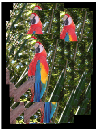
ファイルー>スケッチ例ー>TFT_eSPIー>Genericー>TFT_SPIFFS_BMP に有るデモです。 このデモプログラムは "SPIFFS" を使用しています。Arduino2.3.xでは "SPIFFS" のデータを Upload する手段が無く このままで実行出来ません。そこで "SPIFFS" を "LittleFS" に変更して実行して見ます。下記はデモプログラムのオリジナルです。
// This sketch draws BMP images pulled from SPIFFS onto the TFT. It is an
// an example from this library: https://github.com/Bodmer/TFT_eSPI

// Images in SPIFFS must be put in the root folder (top level) to be found
// Use the SPIFFS library example to verify SPIFFS works!

// The example image used to test this sketch can be found in the sketch
// Data folder, press Ctrl+K to see this folder. Use the IDE "Tools" menu
// option to upload the sketches data folder to the SPIFFS

// This sketch has been tested on the ESP32 and ESP8266

//----------------------------------------------------------------------------------------------------

//====================================================================================
//                                  Libraries
//====================================================================================
// Call up the SPIFFS FLASH filing system this is part of the ESP Core
#define FS_NO_GLOBALS
#include <FS.h>

#ifdef ESP32
  #include "SPIFFS.h"  // For ESP32 only
#endif

// Call up the TFT library
#include <TFT_eSPI.h> // Hardware-specific library for ESP8266

// Invoke TFT library
TFT_eSPI tft = TFT_eSPI();

//====================================================================================
//                                    Setup
//====================================================================================
void setup()
{
  Serial.begin(115200);

  if (!SPIFFS.begin()) {
    Serial.println("SPIFFS initialisation failed!");
    while (1) yield(); // Stay here twiddling thumbs waiting
  }
  Serial.println("\r\nSPIFFS initialised.");

  // Now initialise the TFT
  tft.begin();
  tft.setRotation(0);  // 0 & 2 Portrait. 1 & 3 landscape
  tft.fillScreen(TFT_BLACK);
}

//====================================================================================
//                                    Loop
//====================================================================================
void loop()
{
  int x = random(tft.width()  - 128);
  int y = random(tft.height() - 160);

  drawBmp("/parrot.bmp", x, y);

  delay(1000);
}
//====================================================================================
// Bodmer's BMP image rendering function

void drawBmp(const char *filename, int16_t x, int16_t y) {

  if ((x >= tft.width()) || (y >= tft.height())) return;

  fs::File bmpFS;

  // Open requested file on SD card
  bmpFS = SPIFFS.open(filename, "r");

  if (!bmpFS)
  {
    Serial.print("File not found");
    return;
  }

  uint32_t seekOffset;
  uint16_t w, h, row, col;
  uint8_t  r, g, b;

  uint32_t startTime = millis();

  if (read16(bmpFS) == 0x4D42)
  {
    read32(bmpFS);
    read32(bmpFS);
    seekOffset = read32(bmpFS);
    read32(bmpFS);
    w = read32(bmpFS);
    h = read32(bmpFS);

    if ((read16(bmpFS) == 1) && (read16(bmpFS) == 24) && (read32(bmpFS) == 0))
    {
      y += h - 1;

      bool oldSwapBytes = tft.getSwapBytes();
      tft.setSwapBytes(true);
      bmpFS.seek(seekOffset);

      uint16_t padding = (4 - ((w * 3) & 3)) & 3;
      uint8_t lineBuffer[w * 3 + padding];

      for (row = 0; row < h; row++) {

        bmpFS.read(lineBuffer, sizeof(lineBuffer));
        uint8_t*  bptr = lineBuffer;
        uint16_t* tptr = (uint16_t*)lineBuffer;
        // Convert 24 to 16-bit colours
        for (uint16_t col = 0; col < w; col++)
        {
          b = *bptr++;
          g = *bptr++;
          r = *bptr++;
          *tptr++ = ((r & 0xF8) << 8) | ((g & 0xFC) << 3) | (b >> 3);
        }

        // Push the pixel row to screen, pushImage will crop the line if needed
        // y is decremented as the BMP image is drawn bottom up
        tft.pushImage(x, y--, w, 1, (uint16_t*)lineBuffer);
      }
      tft.setSwapBytes(oldSwapBytes);
      Serial.print("Loaded in "); Serial.print(millis() - startTime);
      Serial.println(" ms");
    }
    else Serial.println("BMP format not recognized.");
  }
  bmpFS.close();
}

// These read 16- and 32-bit types from the SD card file.
// BMP data is stored little-endian, Arduino is little-endian too.
// May need to reverse subscript order if porting elsewhere.

uint16_t read16(fs::File &f) {
  uint16_t result;
  ((uint8_t *)&result)[0] = f.read(); // LSB
  ((uint8_t *)&result)[1] = f.read(); // MSB
  return result;
}

uint32_t read32(fs::File &f) {
  uint32_t result;
  ((uint8_t *)&result)[0] = f.read(); // LSB
  ((uint8_t *)&result)[1] = f.read();
  ((uint8_t *)&result)[2] = f.read();
  ((uint8_t *)&result)[3] = f.read(); // MSB
  return result;
}
- デモプログラムを読み込んだら別名で保存。
- 今回はファイル名を、”TFT_SPIFFS_BMP_littlefs.ino"としました。
- "TFT_SPIFFS_BMP_littlefs.ino" の変更箇所
- 39行の "if (!SPIFFS.begin())" を "if (!LittleFS.begin())" に変更
- #include <LittleFS.h> を追加
- "BMP_functions.ino" の変更箇所
- 10行の "bmpFS = SPIFFS.open(..." を "bmpFS = LittleFS.open(..." に変更
- Upload するデータはスケッチの "data" フォルダに既に保存されています。"LittleFS Uploader" を参考にデータを Upload して下さい。
- 後はコンパイルして実行すればオオムの画像が表示されます
FLASHに保存されたBITMAPファイルを表示する関数は
void drawBmp(const char *filename, int16_t x, int16_t y)
その引数は以下の通り。
| 引数 | 説明 |
|---|---|
| const char *filename | 画像データ開始のポインタ |
| int16_t x | 表示位置X座標(画像左上隅基準) |
| int16_t y | 表示位置Y座標(画像左上隅基準) |
SDカードから読み込み
ファイルシステムを変更すればSDカードに保存したファイルを表示する事も出来ます。 今回はSD_MMCを準備しているので、それに合わせてデモプログラムを変更し見ました。
// This sketch draws BMP images pulled from SPIFFS onto the TFT. It is an
// an example from this library: https://github.com/Bodmer/TFT_eSPI

// Images in SPIFFS must be put in the root folder (top level) to be found
// Use the SPIFFS library example to verify SPIFFS works!

// The example image used to test this sketch can be found in the sketch
// Data folder, press Ctrl+K to see this folder. Use the IDE "Tools" menu
// option to upload the sketches data folder to the SPIFFS

// This sketch has been tested on the ESP32 and ESP8266

//----------------------------------------------------------------------------------------------------

//====================================================================================
//                                  Libraries
//====================================================================================
// Call up the SPIFFS FLASH filing system this is part of the ESP Core
#define FS_NO_GLOBALS
#include <FS.h>

#ifdef ESP32
  #include "SPIFFS.h"  // For ESP32 only
#endif

// Call up the TFT library
#include <TFT_eSPI.h> // Hardware-specific library for ESP8266

#include <SD_MMC.h>
//------------ SD_MMC 1-wire SD mode ----------------------------
#define mmc_CMD         21
#define mmc_CLK         48
#define mmc_D0          47
#define SDMMC_FREQ      30000
#define MAX_FILE        3

// Invoke TFT library
TFT_eSPI tft = TFT_eSPI();

//====================================================================================
//                                    Setup
//====================================================================================
void setup()
{
  Serial.begin(115200);

  // Initialise the SD_MMC
  pinMode(mmc_D0, INPUT_PULLUP);
  SD_MMC.setPins(mmc_CLK, mmc_CMD, mmc_D0);
  if(!SD_MMC.begin("/sdmmc", true, false, SDMMC_FREQ, MAX_FILE)){
     Serial.println("Card Mount Failed");
     return;
  }
  else Serial.println("SD_MMC initialisation OK");

  // Now initialise the TFT
  tft.begin();
  tft.setRotation(0);  // 0 & 2 Portrait. 1 & 3 landscape
  tft.fillScreen(TFT_BLACK);
}

//====================================================================================
//                                    Loop
//====================================================================================
void loop()
{
  int x = random(tft.width()  - 128);
  int y = random(tft.height() - 160);

  drawBmp("/parrot.bmp", x, y);

  delay(1000);
}
//====================================================================================
// Bodmer's BMP image rendering function

void drawBmp(const char *filename, int16_t x, int16_t y) {

  if ((x >= tft.width()) || (y >= tft.height())) return;

  fs::File bmpFS;

  // Open requested file on SD card
  bmpFS = SD_MMC.open(filename, "r");

  if (!bmpFS)
  {
    Serial.print("File not found");
    return;
  }

  uint32_t seekOffset;
  uint16_t w, h, row, col;
  uint8_t  r, g, b;

  uint32_t startTime = millis();

  if (read16(bmpFS) == 0x4D42)
  {
    read32(bmpFS);
    read32(bmpFS);
    seekOffset = read32(bmpFS);
    read32(bmpFS);
    w = read32(bmpFS);
    h = read32(bmpFS);

    if ((read16(bmpFS) == 1) && (read16(bmpFS) == 24) && (read32(bmpFS) == 0))
    {
      y += h - 1;

      bool oldSwapBytes = tft.getSwapBytes();
      tft.setSwapBytes(true);
      bmpFS.seek(seekOffset);

      uint16_t padding = (4 - ((w * 3) & 3)) & 3;
      uint8_t lineBuffer[w * 3 + padding];

      for (row = 0; row < h; row++) {

        bmpFS.read(lineBuffer, sizeof(lineBuffer));
        uint8_t*  bptr = lineBuffer;
        uint16_t* tptr = (uint16_t*)lineBuffer;
        // Convert 24 to 16-bit colours
        for (uint16_t col = 0; col < w; col++)
        {
          b = *bptr++;
          g = *bptr++;
          r = *bptr++;
          *tptr++ = ((r & 0xF8) << 8) | ((g & 0xFC) << 3) | (b >> 3);
        }

        // Push the pixel row to screen, pushImage will crop the line if needed
        // y is decremented as the BMP image is drawn bottom up
        tft.pushImage(x, y--, w, 1, (uint16_t*)lineBuffer);
      }
      tft.setSwapBytes(oldSwapBytes);
      Serial.print("Loaded in "); Serial.print(millis() - startTime);
      Serial.println(" ms");
    }
    else Serial.println("BMP format not recognized.");
  }
  bmpFS.close();
}

// These read 16- and 32-bit types from the SD card file.
// BMP data is stored little-endian, Arduino is little-endian too.
// May need to reverse subscript order if porting elsewhere.

uint16_t read16(fs::File &f) {
  uint16_t result;
  ((uint8_t *)&result)[0] = f.read(); // LSB
  ((uint8_t *)&result)[1] = f.read(); // MSB
  return result;
}

uint32_t read32(fs::File &f) {
  uint32_t result;
  ((uint8_t *)&result)[0] = f.read(); // LSB
  ((uint8_t *)&result)[1] = f.read();
  ((uint8_t *)&result)[2] = f.read();
  ((uint8_t *)&result)[3] = f.read(); // MSB
  return result;
}
変更箇所とコンパイル実行は下記の通り。
- TFT_SPIFFS_BMP.ino
- 29行: ”#include <SD_MMC.h>" の追加
- 30-35行: SD_MMCピン定義
- 47-54行: SD_MMCの初期設定/li>
- BMP_functions.ino
- 10行: ”bmpFS = SD_MMC.open(filename, "r"); SPIFF を SD_MMC に変更
- スケッチのdataフォルダにある、”parrot.bmp" をSDカードのルートにコピーしソケットに挿入。
- コンパイル実行するれば、オームの絵が表示されます。
SDカードから画像を読み込めるとかなり便利です。
JPEG関係
ESP32_SDcard_jpeg.ino
ファイルー>スケッチ例ー>TFT_eSPIー>Genericー>ESP32_SDcard_jpeg にデモプログラムが有ります。 "SPI" 管理の SDカードからデータを読み込む仕様になっているので、それを "SM_MMC" 管理に変更します。 先ずは読み込んだデモプログラムを別名(今回は、”ESP32_SDcard_jpeg_mmc.ino"としました)で保存。 そのスケッチに以下の変更を行っています。
// This sketch if for an ESP32, it draws Jpeg images pulled from an SD Card
// onto the TFT.

// As well as the TFT_eSPI library you will need the JPEG Decoder library.
// A copy can be downloaded here, it is based on the library by Makoto Kurauchi.
// https://github.com/Bodmer/JPEGDecoder

// Images on SD Card must be put in the root folder (top level) to be found
// Use the SD library examples to verify your SD Card interface works!

// The example images used to test this sketch can be found in the library
// JPEGDecoder/extras folder
//----------------------------------------------------------------------------------------------------

#include <SPI.h>

#include <FS.h>
#include <SD.h>

#include <TFT_eSPI.h>
TFT_eSPI tft = TFT_eSPI();

// JPEG decoder library
#include <JPEGDecoder.h>

#include <SD_MMC.h>
//------------ SD_MMC 1-wire SD mode ----------------------------
#define mmc_CMD         21
#define mmc_CLK         48
#define mmc_D0          47
#define SDMMC_FREQ      30000
#define MAX_FILE        3

//####################################################################################################
// Setup
//####################################################################################################
void setup() {
  Serial.begin(115200);

  // Set all chip selects high to avoid bus contention during initialisation of each peripheral
  digitalWrite(38, HIGH); // Touch controller chip select (if used)
  digitalWrite(1, HIGH); // TFT screen chip select
//  digitalWrite( 5, HIGH); // SD card chips select, must use GPIO 5 (ESP32 SS)

  tft.begin();

  // Initialise the SD_MMC
  pinMode(mmc_D0, INPUT_PULLUP);
  SD_MMC.setPins(mmc_CLK, mmc_CMD, mmc_D0);
  if(!SD_MMC.begin("/sdmmc", true, false, SDMMC_FREQ, MAX_FILE)){
     Serial.println("Card Mount Failed");
     return;
  }
  else Serial.println("SD_MMC initialisation OK");
}

//####################################################################################################
// Main loop
//####################################################################################################
void loop() {

  tft.setRotation(2);  // portrait
  tft.fillScreen(random(0xFFFF));

  // The image is 300 x 300 pixels so we do some sums to position image in the middle of the screen!
  // Doing this by reading the image width and height from the jpeg info is left as an exercise!
  int x = (tft.width()  - 300) / 2 - 1;
  int y = (tft.height() - 300) / 2 - 1;

  drawSdJpeg("/EagleEye.jpg", x, y);     // This draws a jpeg pulled off the SD Card
  delay(2000);

  tft.setRotation(2);  // portrait
  tft.fillScreen(random(0xFFFF));
  drawSdJpeg("/Baboon40.jpg", 0, 0);     // This draws a jpeg pulled off the SD Card
  delay(2000);

  tft.setRotation(2);  // portrait
  tft.fillScreen(random(0xFFFF));
  drawSdJpeg("/lena20k.jpg", 0, 0);     // This draws a jpeg pulled off the SD Card
  delay(2000);

  tft.setRotation(1);  // landscape
  tft.fillScreen(random(0xFFFF));
  drawSdJpeg("/Mouse480.jpg", 0, 0);     // This draws a jpeg pulled off the SD Card

  delay(2000);

  while(1); // Wait here
}

//####################################################################################################
// Draw a JPEG on the TFT pulled from SD Card
//####################################################################################################
// xpos, ypos is top left corner of plotted image
void drawSdJpeg(const char *filename, int xpos, int ypos) {

  // Open the named file (the Jpeg decoder library will close it)
  File jpegFile = SD_MMC.open( filename, FILE_READ);  // or, file handle reference for SD library

  if ( !jpegFile ) {
    Serial.print("ERROR: File \""); Serial.print(filename); Serial.println ("\" not found!");
    return;
  }

  Serial.println("===========================");
  Serial.print("Drawing file: "); Serial.println(filename);
  Serial.println("===========================");

  // Use one of the following methods to initialise the decoder:
  bool decoded = JpegDec.decodeSdFile(jpegFile);  // Pass the SD file handle to the decoder,
  //bool decoded = JpegDec.decodeSdFile(filename);  // or pass the filename (String or character array)

  if (decoded) {
    // print information about the image to the serial port
    jpegInfo();
    // render the image onto the screen at given coordinates
    jpegRender(xpos, ypos);
  }
  else {
    Serial.println("Jpeg file format not supported!");
  }
}

//####################################################################################################
// Draw a JPEG on the TFT, images will be cropped on the right/bottom sides if they do not fit
//####################################################################################################
// This function assumes xpos,ypos is a valid screen coordinate. For convenience images that do not
// fit totally on the screen are cropped to the nearest MCU size and may leave right/bottom borders.
void jpegRender(int xpos, int ypos) {

  //jpegInfo(); // Print information from the JPEG file (could comment this line out)

  uint16_t *pImg;
  uint16_t mcu_w = JpegDec.MCUWidth;
  uint16_t mcu_h = JpegDec.MCUHeight;
  uint32_t max_x = JpegDec.width;
  uint32_t max_y = JpegDec.height;

  bool swapBytes = tft.getSwapBytes();
  tft.setSwapBytes(true);

  // Jpeg images are draw as a set of image block (tiles) called Minimum Coding Units (MCUs)
  // Typically these MCUs are 16x16 pixel blocks
  // Determine the width and height of the right and bottom edge image blocks
  uint32_t min_w = jpg_min(mcu_w, max_x % mcu_w);
  uint32_t min_h = jpg_min(mcu_h, max_y % mcu_h);

  // save the current image block size
  uint32_t win_w = mcu_w;
  uint32_t win_h = mcu_h;

  // record the current time so we can measure how long it takes to draw an image
  uint32_t drawTime = millis();

  // save the coordinate of the right and bottom edges to assist image cropping
  // to the screen size
  max_x += xpos;
  max_y += ypos;

  // Fetch data from the file, decode and display
  while (JpegDec.read()) {    // While there is more data in the file
    pImg = JpegDec.pImage ;   // Decode a MCU (Minimum Coding Unit, typically a 8x8 or 16x16 pixel block)

    // Calculate coordinates of top left corner of current MCU
    int mcu_x = JpegDec.MCUx * mcu_w + xpos;
    int mcu_y = JpegDec.MCUy * mcu_h + ypos;

    // check if the image block size needs to be changed for the right edge
    if (mcu_x + mcu_w <= max_x) win_w = mcu_w;
    else win_w = min_w;

    // check if the image block size needs to be changed for the bottom edge
    if (mcu_y + mcu_h <= max_y) win_h = mcu_h;
    else win_h = min_h;

    // copy pixels into a contiguous block
    if (win_w != mcu_w)
    {
      uint16_t *cImg;
      int p = 0;
      cImg = pImg + win_w;
      for (int h = 1; h < win_h; h++)
      {
        p += mcu_w;
        for (int w = 0; w < win_w; w++)
        {
          *cImg = *(pImg + w + p);
          cImg++;
        }
      }
    }

    // calculate how many pixels must be drawn
    uint32_t mcu_pixels = win_w * win_h;

    // draw image MCU block only if it will fit on the screen
    if (( mcu_x + win_w ) <= tft.width() && ( mcu_y + win_h ) <= tft.height())
      tft.pushImage(mcu_x, mcu_y, win_w, win_h, pImg);
    else if ( (mcu_y + win_h) >= tft.height())
      JpegDec.abort(); // Image has run off bottom of screen so abort decoding
  }

  tft.setSwapBytes(swapBytes);

  showTime(millis() - drawTime); // These lines are for sketch testing only
}

//####################################################################################################
// Print image information to the serial port (optional)
//####################################################################################################
// JpegDec.decodeFile(...) or JpegDec.decodeArray(...) must be called before this info is available!
void jpegInfo() {

  // Print information extracted from the JPEG file
  Serial.println("JPEG image info");
  Serial.println("===============");
  Serial.print("Width      :");
  Serial.println(JpegDec.width);
  Serial.print("Height     :");
  Serial.println(JpegDec.height);
  Serial.print("Components :");
  Serial.println(JpegDec.comps);
  Serial.print("MCU / row  :");
  Serial.println(JpegDec.MCUSPerRow);
  Serial.print("MCU / col  :");
  Serial.println(JpegDec.MCUSPerCol);
  Serial.print("Scan type  :");
  Serial.println(JpegDec.scanType);
  Serial.print("MCU width  :");
  Serial.println(JpegDec.MCUWidth);
  Serial.print("MCU height :");
  Serial.println(JpegDec.MCUHeight);
  Serial.println("===============");
  Serial.println("");
}

//####################################################################################################
// Show the execution time (optional)
//####################################################################################################
// WARNING: for UNO/AVR legacy reasons printing text to the screen with the Mega might not work for
// sketch sizes greater than ~70KBytes because 16-bit address pointers are used in some libraries.

// The Due will work fine with the HX8357_Due library.

void showTime(uint32_t msTime) {
  //tft.setCursor(0, 0);
  //tft.setTextFont(1);
  //tft.setTextSize(2);
  //tft.setTextColor(TFT_WHITE, TFT_BLACK);
  //tft.print(F(" JPEG drawn in "));
  //tft.print(msTime);
  //tft.println(F(" ms "));
  Serial.print(F(" JPEG drawn in "));
  Serial.print(msTime);
  Serial.println(F(" ms "));
}
- 26-32行:SD_MMCのパラメター関係。
- 47-55行:SD_MMCの初期設定のみに変更。
- 99行:"SD.open" を "SD_MMC.open" に変更。
コンパイル前に下記を行って下さい。
- 保存したスケッチの "data" フォルダに画像データが有ります。 これらをSDカードのルートにコピーし LCD の SDソケットにセットして下さい。
- このスケッチは "JPEGDecoder.h" 使用をしています。コンパイル前に
" IDEのライブラリアイコン ー> 検索窓に"JPEGDecoder"を入力 ー> 表示された項目をインストール "
でライブラリーをインストールして下さい。
以下は実行結果。LCDに左から右へ画像が順に、リアルモニタに画像のデータが表示されます。

LCDの解像度より画像が大きい場合、LCDの解像度に合わせて画像をクリップしています。
このプログラムでキーとなっている関数は、void drawSdJpeg(const char *filename, int xpos, int ypos)です。
| 引数 | 説明 |
|---|---|
| const char *filename | 画像データ開始のポインタ |
| int x | 表示位置X座標(画像左上隅基準) |
| int y | 表示位置Y座標(画像左上隅基準) |
ここでデータを読み込みデコードを行い、 BITMAP の時と同じ tft.pushImage() 関数を使って LCD に表示しています。 BITMAPの時と同様に関数 ”tft.pushImage()” の引数を1つ増やし透明色を扱えるか試してみました。 下記左は元絵。右は白を透明色に指定した結果です。

JPGでも機能する事が分かりました。
PNG関係
Flash_PNG.ino
IDE でファイルー>スケッチ例ー>TFT_eSPIー>PNG Imagesー>Flash_PNG に有るデモ。 配列 "panda.h" の画像データを表示するスケッチです。
// This example renders a png file that is stored in a FLASH array
// using the PNGdec library (available via library manager).

// Note: The PNGDEC required lots of RAM to work (~40kbytes) so
// this sketch is will not run on smaller memory processors (e.g.
// ESP8266, STM32F103 etc.)

// Image files can be converted to arrays using the tool here:
// https://notisrac.github.io/FileToCArray/
// To use this tool:
//   1. Drag and drop file on "Browse..." button
//   2. Tick box "Treat as binary"
//   3. Click "Convert"
//   4. Click "Save as file" and move the header file to sketch folder
//   5. Open the sketch in IDE
//   6. Include the header file containing the array (panda.h in this example)

// Include the PNG decoder library
#include <PNGdec.h>
#include "panda.h" // Image is stored here in an 8-bit array

PNG png; // PNG decoder instance

#define MAX_IMAGE_WIDTH 240 // Adjust for your images

int16_t xpos = 0;
int16_t ypos = 0;

// Include the TFT library https://github.com/Bodmer/TFT_eSPI
#include "SPI.h"
#include <TFT_eSPI.h>              // Hardware-specific library
TFT_eSPI tft = TFT_eSPI();         // Invoke custom library

//====================================================================================
//                                    Setup
//====================================================================================
void setup()
{
  Serial.begin(115200);
  Serial.println("\n\n Using the PNGdec library");

  // Initialise the TFT
  tft.begin();
  tft.fillScreen(TFT_BLACK);

  Serial.println("\r\nInitialisation done.");
}

//====================================================================================
//                                    Loop
//====================================================================================
void loop()
{
  int16_t rc = png.openFLASH((uint8_t *)panda, sizeof(panda), pngDraw);
  if (rc == PNG_SUCCESS) {
    Serial.println("Successfully opened png file");
    Serial.printf("image specs: (%d x %d), %d bpp, pixel type: %d\n", png.getWidth(), png.getHeight(), png.getBpp(), png.getPixelType());
    tft.startWrite();
    uint32_t dt = millis();
    rc = png.decode(NULL, 0);
    Serial.print(millis() - dt); Serial.println("ms");
    tft.endWrite();
    // png.close(); // not needed for memory->memory decode
  }
  delay(3000);
  tft.fillScreen(random(0x10000));
}


//=========================================v==========================================
//                                      pngDraw
//====================================================================================
// This next function will be called during decoding of the png file to
// render each image line to the TFT.  If you use a different TFT library
// you will need to adapt this function to suit.
// Callback function to draw pixels to the display
void pngDraw(PNGDRAW *pDraw) {
  uint16_t lineBuffer[MAX_IMAGE_WIDTH];
  png.getLineAsRGB565(pDraw, lineBuffer, PNG_RGB565_BIG_ENDIAN, 0xffffffff);
  tft.pushImage(xpos, ypos + pDraw->y, pDraw->iWidth, 1, lineBuffer);
}
- 22行:PNGインスタンスの宣言
- 54行:int16_t rc = png.openFLASH((uint8_t *)panda, sizeof(panda), pngDraw);
- png.openFLASH() この関数で解凍の準備をします。引数は、
引数 説明 uint8_t *data 画像データ開始のポインタ int num データの総バイト数 関数ポインタ *pfunc 描画用コールバック関数のポインタ - 57行:png.openFLASH() が成功すると、
- デコードに必要なデータが "png" インスタンスに保存されます。
- ここでデータの一部(画像の縦、横等)を表示しています。
- 58行:LCDへの書き込み準備
- 60行:rc = png.decode(NULL, 0);
- ここでデータのデコードを行います。引数は、
通常(NULL,0)で問題ないようです。
引数 説明 void *pUser ユーザー定義データへのポインタ int iOptions デコードオプション - ここでは画像の1行分をデコードして表示用の関数 "pngDraw()" へデータを渡します。
- デコードを最後まで行うと戻り値を返して終了。
- ここでデータのデコードを行います。引数は、
- 62行:LCDへの書き込み完了
- 77行:void pngDraw(PNGDRAW *pDraw)
- これは "png.decode()" からの CALL_BACK 関数です。
- ここで1行分のデータがLCDに書き込まれます。
- 80行:tft.pushImage(xpos, ypos + pDraw->y, pDraw->iWidth, 1, lineBuffer);
- ここで画像の書き出し位置の指定に外部変数 "xpos", "ypos" が使われています。
スケッチで ”PNGdec.h” を使用しているのでライブラリーをインストール。 冒頭のコメントで "メモリーが少ないと動かない" とあるので、IDE の "Partition scheme" を "Huge APP" にして コンパイルするとなんとエラーが出ました。エラーの内容は、

”panda.h”は、PNGファイルそのものでした。ということは、"PNG" 形式の画像データを16進表記のテキスト に変えて、"panda.h" の配列 "panda[]" に入れれば画像が表示出来ると思われます。 そこでSDカードに 保存した"PNG" 形式の画像データを16進テキストファイルに変換してSDカードに保存する スケッチを書いて見ました。
#include "SPI.h"
#include <FS.h>
#include <SD_MMC.h>
//------------ SD_MMC 1-wire SD mode ----------------------------
#define mmc_CMD         21
#define mmc_CLK         48
#define mmc_D0          47
#define SDMMC_FREQ      30000
#define MAX_FILE        3

void setup() {
  int a;
  uint8_t buf[10];

    Serial.begin(115200);

    pinMode(mmc_D0, INPUT_PULLUP);
    SD_MMC.setPins(mmc_CLK, mmc_CMD, mmc_D0);
    if(!SD_MMC.begin("/sdmmc", true, false, SDMMC_FREQ, MAX_FILE)){
       Serial.println("Card Mount Failed");
      return;
    }
    else Serial.println("SD_MMC initialisation OK");

    File fp = SD_MMC.open("/parrot.png",FILE_READ);
    File fp1 = SD_MMC.open("/temp.txt",FILE_WRITE);
    a = 0;
    sprintf((char*)buf,"0x%02x",fp.read());
    fp1.write(buf,4);
    while (fp.available()){
      sprintf((char*)buf,",0x%02x",fp.read());
      fp1.write(buf,5);
      a ++;
      if(a == 50){
        fp1.write('\n');
        a = 0;
      }
    }
    fp.close();
    fp1.close();
    Serial.println("OK");

}

void loop() {
  // put your main code here, to run repeatedly:

}
JPEGのサンプル画像、"parrot.jpg" を "PNG" 形式で SDカードに保存。スケッチを実行し 出来た "/temp.txt" の中身を "Flash_PNG.ino" の ”panda[]” に代入し、 コンパイル実行したらオームの画像が表示されました。想定通りでした。
LittleFS_PNG.ino
LittleFSでFLASHに保存されたPNG形式の絵を表示するデモです。 ファイルー>スケッチ例ー>TFT_eSPIー>PNG Imagesー>LittleFS_PNG に有ります。
// This example if for processors with LittleFS capability (e.g. RP2040,
// ESP32, ESP8266). It renders a png file that is stored in LittleFS
// using the PNGdec library (available via library manager).

// Note: The PNGDEC required lots of RAM to work (~40kbytes) so
// this sketch is will not run on smaller memory processors (e.g.
// ESP8266, STM32F103 etc.)

// The test image is in the sketch "data" folder (press Ctrl+K to see it).
// You must upload the image to LittleFS using the Arduino IDE Tools Data
// Upload menu option (you may need to install extra tools for that).

// Don't forget to use the Arduino IDE Tools menu to allocate a LittleFS
// memory partition before uploading the sketch and data!

#include <LittleFS.h>
#define FileSys LittleFS

// Include the PNG decoder library
#include <PNGdec.h>

PNG png;
#define MAX_IMAGE_WIDTH 240 // Adjust for your images

int16_t xpos = 0;
int16_t ypos = 0;

// Include the TFT library https://github.com/Bodmer/TFT_eSPI
#include "SPI.h"
#include <TFT_eSPI.h>              // Hardware-specific library
TFT_eSPI tft = TFT_eSPI();         // Invoke custom library

//====================================================================================
//                                    Setup
//====================================================================================
void setup()
{
  Serial.begin(115200);
  Serial.println("\n\n Using the PNGdec library");

  // Initialise FS
  if (!FileSys.begin()) {
    Serial.println("LittleFS initialisation failed!");
    while (1) yield(); // Stay here twiddling thumbs waiting
  }

  // Initialise the TFT
  tft.begin();
  tft.fillScreen(TFT_BLACK);

  Serial.println("\r\nInitialisation done.");
}

//====================================================================================
//                                    Loop
//====================================================================================
void loop()
{
  // Scan LittleFS and load any *.png files
  File root = LittleFS.open("/", "r");
  while (File file = root.openNextFile()) {
    String strname = file.name();
    strname = "/" + strname;
    Serial.println(file.name());
    // If it is not a directory and filename ends in .png then load it
    if (!file.isDirectory() && strname.endsWith(".png")) {
      // Pass support callback function names to library
      int16_t rc = png.open(strname.c_str(), pngOpen, pngClose, pngRead, pngSeek, pngDraw);
      if (rc == PNG_SUCCESS) {
        tft.startWrite();
        Serial.printf("image specs: (%d x %d), %d bpp, pixel type: %d\n", png.getWidth(), png.getHeight(), png.getBpp(), png.getPixelType());
        uint32_t dt = millis();
        if (png.getWidth() > MAX_IMAGE_WIDTH) {
          Serial.println("Image too wide for allocated line buffer size!");
        }
        else {
          rc = png.decode(NULL, 0);
          png.close();
        }
        tft.endWrite();
        // How long did rendering take...
        Serial.print(millis()-dt); Serial.println("ms");
      }
    }
    delay(3000);
    tft.fillScreen(random(0x10000));
  }
}


//=========================================v==========================================
//                                      pngDraw
//====================================================================================
// This next function will be called during decoding of the png file to
// render each image line to the TFT.  If you use a different TFT library
// you will need to adapt this function to suit.
// Callback function to draw pixels to the display
void pngDraw(PNGDRAW *pDraw) {
  uint16_t lineBuffer[MAX_IMAGE_WIDTH];
  png.getLineAsRGB565(pDraw, lineBuffer, PNG_RGB565_BIG_ENDIAN, 0xffffffff);
  tft.pushImage(xpos, ypos + pDraw->y, pDraw->iWidth, 1, lineBuffer);
}
- 68行の "png.open()" がキー関数です。この関数の引数は以下の通り。
- 後はほとんど同じですが、77行に "png.close();" が有ります。ファイルを閉じる関数です。
| 引数 | 説明 |
|---|---|
| const char * | ファイル名(パスを含む) |
| PNG_OPEN_CALLBACK | ファイルを開く関数 |
| PNG_CLOSE_CALLBACK | ファイルを閉じる関数 |
| PNG_READ_CALLBACK | データを読み出す関数 |
| PNG_SEEK_CALLBACK | 読み取り位置を移動する関数 |
| PNG_DRAW_CALLBACK | 描画を実行する関数 |
スケッチで "LittleFS.h" を使用しているのでそれをインストール。予め画像データを "LittleFS Uploader" を参照にUploadして下さい。 このスケッチの "void pngDraw()" も型を "int" に変えて最後に "return 1;" を追加して下さい。
コンパイル実行でスケッチは起動します。LCDに "パンダ" と "鷹の目" が交互に表示されます。
SDカードから読み込む
"LittleFS" を "SD_MMC" に変更すればSDカードから読み込めるはずです。そこでスケッチを下記の様に書きかました
// This example if for processors with LittleFS capability (e.g. RP2040,
// ESP32, ESP8266). It renders a png file that is stored in LittleFS
// using the PNGdec library (available via library manager).

// Note: The PNGDEC required lots of RAM to work (~40kbytes) so
// this sketch is will not run on smaller memory processors (e.g.
// ESP8266, STM32F103 etc.)

// The test image is in the sketch "data" folder (press Ctrl+K to see it).
// You must upload the image to LittleFS using the Arduino IDE Tools Data
// Upload menu option (you may need to install extra tools for that).

// Don't forget to use the Arduino IDE Tools menu to allocate a LittleFS
// memory partition before uploading the sketch and data!
#include <SD_MMC.h>
#define FileSys SD_MMC

//------------ SD_MMC 1-wire SD mode ----------------------------
#define mmc_CMD         21
#define mmc_CLK         48
#define mmc_D0          47
#define SDMMC_FREQ      30000
#define MAX_FILE        3

// Include the PNG decoder library
#include <PNGdec.h>

PNG png;
#define MAX_IMAGE_WIDTH 240 // Adjust for your images

int16_t xpos = 0;
int16_t ypos = 0;

// Include the TFT library https://github.com/Bodmer/TFT_eSPI
#include "SPI.h"
#include <TFT_eSPI.h>              // Hardware-specific library
TFT_eSPI tft = TFT_eSPI();         // Invoke custom library

//====================================================================================
//                                    Setup
//====================================================================================
void setup()
{
  Serial.begin(115200);
  Serial.println("\n\n Using the PNGdec library");

    // Initialise the SD_MMC
    pinMode(mmc_D0, INPUT_PULLUP);
    SD_MMC.setPins(mmc_CLK, mmc_CMD, mmc_D0);

    // Initialise FS
    if(!FileSys.begin("/sdmmc", true, false, SDMMC_FREQ, MAX_FILE)){
    Serial.println("SD_MMC initialisation failed!");
    while (1) yield(); // Stay here twiddling thumbs waiting
  }

  // Initialise the TFT
  tft.begin();
  tft.fillScreen(TFT_BLACK);

  Serial.println("\r\nInitialisation done.");
}

//====================================================================================
//                                    Loop
//====================================================================================
void loop()
{
  // Scan LittleFS and load any *.png files
  File root = SD_MMC.open("/", "r");
  while (File file = root.openNextFile()) {
    String strname = file.name();
    strname = "/" + strname;
    Serial.println(file.name());
    // If it is not a directory and filename ends in .png then load it
    if (!file.isDirectory() && strname.endsWith(".png")) {
      // Pass support callback function names to library
      int16_t rc = png.open(strname.c_str(), pngOpen, pngClose, pngRead, pngSeek, pngDraw);
      if (rc == PNG_SUCCESS) {
        tft.startWrite();
        Serial.printf("image specs: (%d x %d), %d bpp, pixel type: %d\n", png.getWidth(), png.getHeight(), png.getBpp(), png.getPixelType());
        uint32_t dt = millis();
        if (png.getWidth() > MAX_IMAGE_WIDTH) {
          Serial.println("Image too wide for allocated line buffer size!");
        }
        else {
          rc = png.decode(NULL, 0);
          png.close();
        }
        tft.endWrite();
        // How long did rendering take...
        Serial.print(millis()-dt); Serial.println("ms");
      }
    }
    delay(3000);
    tft.fillScreen(random(0x10000));
  }
}


//=========================================v==========================================
//                                      pngDraw
//====================================================================================
// This next function will be called during decoding of the png file to
// render each image line to the TFT.  If you use a different TFT library
// you will need to adapt this function to suit.
// Callback function to draw pixels to the display
int pngDraw(PNGDRAW *pDraw) {
  uint16_t lineBuffer[MAX_IMAGE_WIDTH];
  png.getLineAsRGB565(pDraw, lineBuffer, PNG_RGB565_BIG_ENDIAN, 0xffffffff);
  tft.pushImage(xpos, ypos + pDraw->y, pDraw->iWidth, 1, lineBuffer);
  return 1;
}
修正後、SDカードのルートに "EagleEye.png" "panda.png" を保存してコンパイル実行して下さい。 同じ様に、LCDに "パンダ" と "鷹の目" が交互に表示されます。
ここでも関数 "tft.pushImage()" が表示に使用されているので、引数を足して透明化を試して見ました。 試した画像は前回と同じ "Arduino" マーク です。結果は想定通り機能しました。

次回は
"bmp"、 "jpg"、 "png" 形式の画像を、メモリー、Flash、SDカードから読み込みLCDに表示出来る様になりました。 LCDの解像度が 320x240 なので、それなりグラフィックが楽しめそうです。
次回は、"Sprite" を予定しています。